Tutorial: Basic principles of animation. Making movies with PyMol.
Using PyMol to animate structural superimposition of biological macromolecules.
With an example on the alpha/beta-hydrolases.
Summary
This tutorial was written to illustrate how to animate structural alignment of protein 3D-models using PyMol. Additionally, it explains basic steps to "construct" any animation you may want to create. As an example the animation of structural superimposition of a lipase (Candida antarctica lipase B, PDB:1TCB) and Human Dipeptidyl peptidase IV (PDB: 1J2E) was made.
Background
The alpha/beta-hydrolase fold superfamily is one of the largest groups of enzymes with diverse catalytic function that share common structural framework and appear to be related by divergent evolution. Comparative bioinformatic analysis of alpha/beta-hydrolases with lipase and protease activities was performed to study why lipases do not hydrolase amides despite wide spread of protease activities within the α/β-hydrolase fold. While subunit size and oligomeric organization of lipases and peptidases can vary they all share conserved structural core and contain three topologically similar residues that form a catalytic triad (a nucleophile, catalytic acid and histidine). Application of the bioinformatic analysis to design alpha/beta-hydrolases with improved functional properties has been discussed in this publication.
Do you want to build a large structure-guided sequence alignment of your protein families automatically?
You can use the Mustguseal server to automatically construct large multiple alignments of protein families from all available information about their structures and sequences in public databases - all you need is to submit a single query protein as a PDB ID. Multiple alignments of thousands of protein sequences and structures can be automatically constructed using that public web-server.
Internet bandwidth notice
This tutorial page contains animated GIF movies that weight about 30 MB in total. Depending on the speed of your internet connection it can take time for them to download to your computer. Until that, the animations can play in a slow mode or not play at all. Do not reload the page and let all files to download to your computer.
THIS WEB-SITE/WEB-SERVER/SOFTWARE IS PROVIDED “AS IS”, WITHOUT WARRANTY OF ANY KIND, EXPRESS OR IMPLIED, INCLUDING BUT NOT LIMITED TO THE WARRANTIES OF MERCHANTABILITY, FITNESS FOR A PARTICULAR PURPOSE AND NONINFRINGEMENT. IN NO EVENT SHALL THE AUTHORS OR COPYRIGHT HOLDERS OR HARDWARE OWNERS OR WEB-SITE/WEB-SERVER/SOFTWARE MAINTEINERS/ADMINISTRATORS BE LIABLE FOR ANY CLAIM, DAMAGES OR OTHER LIABILITY, WHETHER IN AN ACTION OF CONTRACT, TORT OR OTHERWISE, ARISING FROM, OUT OF OR IN CONNECTION WITH THE WEB-SITE/WEB-SERVER/SOFTWARE OR THE USE OR OTHER DEALINGS IN THE WEB-SITE/WEB-SERVER/SOFTWARE. PLEASE NOTE THAT OUR WEBSITE COLLECTS STANDARD APACHE2 LOGS, INCLUDING DATES, TIMES, IP ADDRESSES, AND SPECIFIC WEB ADDRESSES ACCESSED. THIS DATA IS STORED FOR APPROXIMATELY ONE YEAR FOR SECURITY AND ANALYTICAL PURPOSES. YOUR PRIVACY IS IMPORTANT TO US, AND WE USE THIS INFORMATION SOLELY FOR WEBSITE IMPROVEMENT AND PROTECTION AGAINST POTENTIAL THREATS. BY USING OUR SITE, YOU CONSENT TO THIS DATA COLLECTION.
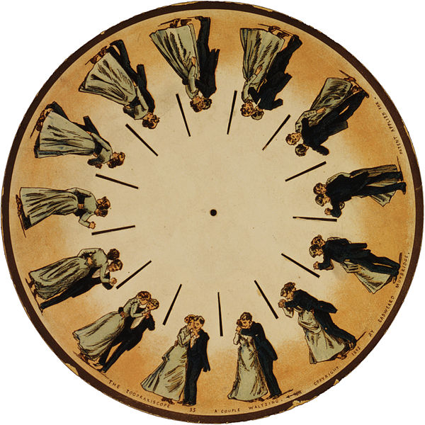
| Basic concept of animation Invention of the phenakistoscope in 1832 was one of the key steps that marked the beginning of cinematography. The phenakistoscope used a disc that contained a series of drawings showing phases of the animation. Spinning of the disc around a center point caused rapid succession of the images that appeared to be a single moving picture to the viewer. The development of cinematography went far beyond this technique, however the basic principle remained. We will use it to animate our protein structures. Since PyMol has a built-in command line API that is based on python language we dont need to create hundreds of frames by hand but instead can write a script. The idea of the script is to calculate a path from one user-defined scene to another, split it into frames and record them to the hard drive. We can later merge these files to create a movie. As with every other movie the first thing you need is a good scenario. You have to think what would you want to show in this animation and then define clear breakpoints that can be used to split the motion into several block steps. Considering the structural superimposition of two proteins the first thing we want is to simulate the alignment itself to make people actually see this process not just the final result. Another thing we would like to do is to zoom on some specific regions of the protein alignment, for example, to show how the active sites superimpose. Finally, in between we can use simple rotation around one axis to explain important features or simply give some time for us to speak. Here we decribe in details the PyMol script that was used to create the image shown on the top of the page. It has three general parts. First part defines global variables and imports external methods, in case of PyMol, for the python interpreter. Second part defines the basic methods that will animate independent blocks of our movie - methods to perform rotation, zoom, superimposition, etc. Usually, you would not modify the content of these methods but you could add new ones to match a particular purpose. Finally, in the third part the basic methods are combined in a user-defined scenario. To my opinion, doing animations by a script is the most flexible option. It allows you to re-run it with different settings and easily edit your scenario. Moreover, the same script can be easily ported to a different situation (different protein molecule). |
Images regarding Phenakistoscope were taken from http://en.wikipedia.org/wiki/Phenakistoscope. |
Starting the script: defining global variables and methods
from __future__ import division
import os
import sys
import re
from math import *

#Define ray tracing resolution
ray_x=640 #Use 1280 for high quality or 320 for testing
ray_y=512 #Use 1024 for high quality or 256 for testing

#Define ray trace options
ray_mode=0
ray_shadows=0
ray_antialias=1 #Set to 0 for faster processing
ray_ambient=0.3 #Comment out with '#' sign here and in ray() to use the default light
ray_save_dpi=72

#Start frame counter
frame_number=1

#Define the method to ray trace the frame and dump image to the hard drive
def ray():
    global ray_x, ray_y, ray_mode, ray_antialias, ray_save_dpi, frame_number
    #Set ray tracer options
    cmd.set("ray_shadows", ray_shadows)
    cmd.set("ambient", ray_ambient)#Comment out with '#' sign to use the default light
    cmd.set("ray_trace_mode", ray_mode)
    #Run ray tracer
    cmd.ray(ray_x, ray_y, ray_antialias)
    #Save image
    cmd.png("mov"+`frame_number`, dpi=ray_save_dpi)
    frame_number+=1

#Set the camera view accoring to 18-point matrix
#Use get_view method in PyMol command line to get the matrix
#@x 18-point PyMol view matrix
def setView (x):
    view=""
    for i in range(len(x)):
        view+=`x[i]`
        if (i != (len(x)-1)):
            view+=","
    cmd.set_view(view)
Basic animation methods
| Rotation in place Rotation in place around the Y-axis is the very basic animation technique that you can use to describe different features of you structure or simply create a nice looking picture to background your talk. PyMol has a built-in set of commands to create the roll animation. However, we will make our own method to have all actions inside one flexible script.
#Rotate an object 360 degrees
#@frames: number of frames to animate (integer)
#@rotation_axis: axis to rotate the structure ('x', 'y' or 'z')
#@originpoint: center of rotation
#(can be a PyMol object or a particular residue/atom)
def roll (frames, rotation_axis, originpoint):
    #Set rotation center to user-defined "originpoint"
    cmd.origin(originpoint)
    #Define the angle to rotate per frame
    angle=360/frames
    frame=1
    #Loop over frames, make a small rotation,
    #ray trace the scene and save the image
    while frame <= frames:
        #Use PyMol rotation function
        cmd.rotate(rotation_axis, angle)
        #Ray trace and save current scene
        ray()
        frame+=1
|
 |
| Rotation with two independent rotation centers Rotation around one axis is OK when you have just one central object that you want to focus the attention on. But what if you have two different objects? Rolling them around the center point can can look strange and make you audience to lose the focus. Consequently, you have to rotate them independently. The method is given below. You can use the code as template to rotate three or more independent objects.
#Rotate two different objects 360 degrees aroung thier axes
#@frames: number of frames to animate (integer)
#@rotation_axis: axis to rotate the structure ('x', 'y' or 'z')
#@obj1: first object (protein molecule)
#@obj2: second object (protein molecule)
def two_roll (frames, rotation_axis, obj1, obj2):
    angle=360/frames
    frame=1
    #Loop over frames, make small rotation to each object,
    #ray trace the scene and save the image
    while frame <= frames:
        #Set rotation center to object1
        cmd.origin(obj1)
        #Rotate object1
        cmd.rotate(rotation_axis, angle, obj1)
        #Set rotation center to object2
        cmd.origin(obj2)
        #Rotate object2
        cmd.rotate(rotation_axis, angle, obj2)
        #Ray trace and save the image
        ray()
        frame+=1
|
 |
| Simulation of structural superimposition The key idea of this part is that the method takes for input a superimposition of two protein structures. In other words the two proteins must be already aligned prior to running this method. The reason for this is that superimposing two biological macromolecules should not be considered as creating a nice picture, but as a computationally and scientifically demanding task that should be done using appropriate bioinformatic software (Example: Matt, Mustang, etc.) and checked manually afterwords. The first step of this animation method is to "de-align" the proteins by translating each molecule in the opposite direction from each other. At this point the first image in captured. Then the two molecules are rotated in place using the method recently discussed on this page. Then the script performs backwards translation of the images to align them - this step is split into many frames to make the transition smooth. Also, rotation is added to each structure while moving. The method ends in the same position it has started - two aligned protein molecules.
#Simulates alignment of two protein structures.
#The method should be used on two already superimposed molecules
#@frames_roll - number of frames to animate rotation
#               of two de-alinged molecules
#@frames_align - number of frames to animate superimposition
#@obj1: first object (protein molecule)
#@shift_x1: shift the first object to the left to de-align
#@obj2: second object (protein molecule)
#@shift_x2: shift the second object to the right to de-align
#@rotation_axis: axis to rotate the structures ('x', 'y' or 'z')
def align(frames_roll, frames_align,
          obj1, shift_x1,
          obj2, shift_x2, rotation_axis):
    #De-align protein molecules
    #Shift the first molecule to the left
    cmd.translate("\"[-"+`shift_x1`+", 0, 0]\"", obj1)
    #Shift the second molecule to the right
    cmd.translate("\"["+`shift_x2`+", 0, 0]\"", obj2)
    #Take the first snapshot in de-aligned state
    ray()

    #Roll two de-aligned molecules in place
    two_roll(frames_roll, 'y', obj1, obj2)

    #Animate superimposition
    angle=360/frames_align
    frame=1
    while (frame <= frames_align):
        #Define translation per frame
        cmd.translate
             ("\"["+`shift_x1/frames_align`+", 0, 0]\"", obj1)
        cmd.translate
             ("\"[-"+`shift_x2/frames_align`+", 0, 0]\"", obj2)

        #Define rotation per frame
        cmd.origin(obj1)
        cmd.rotate(rotation_axis, angle, obj1)
        cmd.origin(obj2)
        cmd.rotate(rotation_axis, angle, obj2)

        #Create the image
        ray()
        frame+=1
|
 |
| Changing the viewpoint Finally, we need a method to trace a smooth path between two user-defined camera views. This method can be used to slightly zoom in to avoid large blank spaces around the central image (for example, when the two structures were de-aligned you need to zoom out to capture the scene, but after proteins got aligned you may want to zoom back in). Moreover, the method can be used to change the view from full-size structure to a particular substructure - for example, the active site of an enzyme. The latter case is more complicated from mathematical point of view and will use slerp (Spherical Linear Interpolation). The method takes for input the 18-point view matrix of the starting frame, 18-point matrix of the target frame and number of frames to split the transition. To use the method simply choose the starting image in your PyMol viewer and then use get_view command to get the 18-point matrix. Then do the same with the target scene. Finally, 30-60 frames would be enough for smooth transition in most cases.
#Changes position of the camera
#@frames: number of frames to animate
#@x: view matrix of the starting frame
#@y: view matrix of the target frame
def changeView (frames,x,y):

    setView(x)
    ray()

    #get quaternions for interpolation
       #between starting and target scenes
    qstart = mat2quat(x[0:9])
    qend = mat2quat(y[0:9])

    frame=1
    while frame <= frames:
        n=[]

        qcur = slerp(qstart, qend, frame/frames)
        matcur = quat2mat(qcur)

        for i in range(9):
            update=matcur[i]
            if abs(update) < 0.001:
		update = 0
            n.insert(i, update)

        for i in range(len(x)):
	    if (i>8):
		update=x[i] + (y[i] - x[i]) * (frame/frames)
		if abs(update) < 0.001:
		  update = 0
                n.insert(i, update)

        setView(n)
        frame+=1
        ray()

#----------------------------------------------------------
#Methods to perform Spherical Linear Interpolation (SLERP)
#The code has been translated to python from sources
#available at http://www.euclideanspace.com/maths/
#          algebra/realNormedAlgebra/quaternions/slerp/
#----------------------------------------------------------
def slerp(qa, qb, t):
    qm=[]

    #Calculate angles between quaternions
    cosHalfTheta = qa[0] * qb[0] + qa[1] * qb[1]
                           + qa[2] * qb[2] + qa[3] * qb[3]
    #if qa=qb or qa=-qb then theta = 0 and we can return qa

    if (cosHalfTheta < 0):
        for i in range(4):
            qb[i] = -qb[i];
        cosHalfTheta = -cosHalfTheta

    if (abs(cosHalfTheta) >= 1.0):
        for i in range(4):
            qm.insert(i,qa[i])
        return qm

    #Calculate temporary values
    halfTheta = acos(cosHalfTheta)
    sinHalfTheta = sqrt(1.0 - cosHalfTheta*cosHalfTheta)

    if (fabs(sinHalfTheta) < 0.000005):
    #fabs is floating point absolute
        for i in range(4):
            qm.insert(i, qa[i] * 0.5 + qb[i] * 0.5)
        return qm

    ratioA = sin((1 - t) * halfTheta) / sinHalfTheta
    ratioB = sin(t * halfTheta) / sinHalfTheta
    #calculate Quaternion
    for i in range(4):
        qm.insert(i, qa[i] * ratioA + qb[i] * ratioB)
    return qm

def mat2quat(m):

    tr = m[0] + m[4] + m[8]

#    m00=0 m01=1 m02=2
#    m10=3 m11=4 m12=5
#    m20=6 m21=7 m22=8

    if (tr > 0):
      S = sqrt(tr+1) * 2;
      qw = 0.25 * S;
      qx = (m[7] - m[5]) / S;
      qy = (m[2] - m[6]) / S;
      qz = (m[3] - m[1]) / S;

    elif ((m[0] > m[4])&(m[0] > m[8])):
      S = sqrt(1 + m[0] - m[4] - m[8]) * 2
      qw = (m[7] - m[5]) / S;
      qx = 0.25 * S;
      qy = (m[1] + m[3]) / S;
      qz = (m[2] + m[6]) / S;

    elif (m[4] > m[8]):
      S = sqrt(1 + m[4] - m[0] - m[8]) * 2
      qw = (m[2] - m[6]) / S;
      qx = (m[1] + m[3]) / S;
      qy = 0.25 * S;
      qz = (m[5] + m[7]) / S;

    else:
      S = sqrt(1 + m[8] - m[0] - m[4]) * 2
      qw = (m[3] - m[1]) / S;
      qx = (m[2] + m[6]) / S;
      qy = (m[5] + m[7]) / S;
      qz = 0.25 * S;

    return [qx,qy,qz,qw]


def quat2mat( Q ):

    xx = Q[0]*Q[0]
    xy = Q[0]*Q[1]
    xz = Q[0]*Q[2]
    xw = Q[0]*Q[3]
    yy = Q[1]*Q[1]
    yz = Q[1]*Q[2]
    yw = Q[1]*Q[3]
    zz = Q[2]*Q[2]
    zw = Q[2]*Q[3]


    M = [1.0 - 2*yy - 2*zz,
         2*xy - 2*zw,
         2*xz + 2*yw,
        2*xy + 2*zw,
        1 - 2*xx - 2*zz,
        2*yz - 2*xw,
        2*xz - 2*yw,
        2*yz + 2*xw,
        1 - 2*xx - 2*yy]

    return M
|
 |
Writing user-defined animation scenario
Finally, its time to bring the basic methods we`ve just discussed to work. First, find the scene you want to begin with. Type get_view in PyMol command line and copy the resulting 18-point view matrix to the script. It contains the 3D coordinates of the camera, but also other settings like front and rear plane distances from the camera. This will be our starting frame.
setView([0.913405001,    0.009108904,   -0.404045910,
     0.199869096,    0.857655287,    0.471460521,
     0.351102561,   -0.511840045,    0.782457471,
    -0.186222672,   -1.656485915, -355.204223633,
    45.377914429,   22.392894745,   81.392692566,
   300.970520020,  402.013854980,  -20.000000000])
Now its time to remember that we have a structural superimposition of two molecules. Thus, we use the method to simulate the alignment. First, the two objects - PDB files 1tcb and 1j2e - will be each moved 30 points in different directions. Then the two objects will roll in place for 90 frames. Meanwhile we can talk about different shape and size of the molecules. Then the alignment is simulated for another 45 frames. All the frames will be captured and written to the hard drive. You need to be sure that the viewpoint you have set in the begining of your scenario will fit the de-aligned images. Eigher test it in PyMol or use low resolution setting of the ray-tracer in the ray() method - it will speed up animation and let you make a low resolution movie very fast.
align(90, 45, '1tcb', 30, '1j2e', 30, 'y')
Now, when using setView command in the beginning of our scenario we have considered that the two proteins will be de-alined during frame capture. Now since they are aligned again we can zoom in. Do it first in the PyMol viewer and then copy-paste the 18-point matrix of the target scene into the script. The transition is set to 30 frames.
changeView(30,

    [0.913405001,    0.009108904,   -0.404045910,
     0.199869096,    0.857655287,    0.471460521,
     0.351102561,   -0.511840045,    0.782457471,
    -0.186222672,   -1.656485915, -355.204223633,
    45.377914429,   22.392894745,   81.392692566,
   300.970520020,  402.013854980,  -20.000000000],

    [0.913405001,    0.009108904,   -0.404045910,
    0.199869096,    0.857655287,    0.471460521,
     0.351102561,   -0.511840045,    0.782457471,
     0.000000000,    0.000000000, -256.684509277,
    28.279685974,   22.153846741,   77.451515198,
   206.162841797,  307.206085205,  -20.000000000])
Its time to make a slow 360-degress rotation and explain our alignment to the audience. Rotation around Y-axis seems more convenient and 1tcb structure is chosen as center of rotation cause its smaller. Setting the rotation to 120 frames will do the job.
roll(120, 'y', '1tcb')
Since we have discussed the full-structure alignment it is now time to look at the active site and discuss superimposition of the catalytic triad residues. Manually choose the target scene in the PyMol viewer and get the 18-point view matrix with get_view command. Dont forget to set the fog, front/rear camera planes etc. - this is all included into the view matrix and will be reproduced during animation. Set the transition to 45 frames. You can first run it in low resolution to check if 45 frames would be enough for smooth animation.
changeView(45,
     [0.913405001,    0.009108904,   -0.404045910,
     0.199869096,    0.857655287,    0.471460521,
     0.351102561,   -0.511840045,    0.782457471,
     0.000000000,    0.000000000, -256.684509277,
    28.279685974,   22.153846741,   77.451515198,
   206.162841797,  307.206085205,  -20.000000000],

    [-0.245052531,    0.443468809,    0.860734820,
     0.717557430,    0.679393291,   -0.145888939,
    -0.650069058,    0.582493782,   -0.485329747,
     0.000000000,    0.000000000,  -44.810520172,
    34.562198639,   28.321912766,   79.162284851,
    39.730285645,   49.890754700,  -19.999998093])
Finally, a slow 360-degrees rotation brings a good overview of the active sites superimposition and gives time for a comment. Nitrogen atom of a catalytic histidine has been chosen as rotation center around Y-axis.
roll(120, 'y', '1tcb and resid 224 and name NE2')
Save the script and get ready to launch.
Running it yourself
1. Download the starting superimposition of the two proteins here. Its a PyMol pse-session file created with PyMol v.1.4.1.
2. Download the animation script pymol_movie.py.
3. Open pse file in pymol, switch to the command line and type
run pymol_movie.py
Before doing this make sure that you PyMol viewer is switched to image mode, not the command line mode!
Press 'Esc' key to toggle between the modes. If the viewer is in the command line mode when ray-tracing you will result with beautiful frames of your command line interpreter.
4. The frame tracing step will take time. If you run a new script for the first time you can use low resolution settings for ray traces (check the ray() method) but be sure to keep the proportions. For example, you can create a test set with 640x512 or even 320x256 resolution and eventually use 1280x1024 or 2560x2048 to get final HQ images. Alternatively, you can comment out the cmd.ray() command in the ray() method. This will make raw untraced images to be saved to the disk in screen resolution. This is the fastest option but if the screen resolution has different proportions with the target resolution you would finally use than the viewer can fail to capture the compete scene.
5. If you have done everything correctly, you should have 453 images in PNG format on your hard drive. In linux OS use the following command to convert PNG files and create animated GIF:
convert -delay 7 -loop 0 `ls *png | sort -V` full.gif
Animated GIF is the most flexible format and never fails to play in presentations (to my experience). Use larger "delay" numbers to slow down your animation or smaller ones - to speed it up. Loop '0' means that once the animation reaches the end frame it will be played again from the beginning. If you want it to stop at the last frame use '-loop 1'. Finally the ls *png | sort -V trick will arrange your files by frame version number from 1-st to 453-rd - this is the way you need it. Alternatively, you can use something more complicated like convert -delay 7 -loop 0 `i=1; while [ "$i" -lt "454" ];do echo -n mov$i.png" "; let i=i+1; done` full_hq.gif. Wondering why not to use "*png" instead? Try out ls *png in your linux command line interpreter. You will see that your frames are arranged according to general numeric order: mov100.png, mov101.png, mov102.png, ..., mov99.png, mov9.png. Merging frames in this order will screw up the movie. Of course, you can use any other software to merge these files to any movie format.
Hope this was a helpful reading.
More to come.
Questions and comments appreciated to
Dmitry